Recast-入门
Recast-Navigation 在做3d游戏的时候,用于做导航的在Unity3D、Unreal Engine都可以使用。当前使用 unreal 4.25
1. Recast工程介绍
RecastNavigation 是一个的导航寻路工具集,它包括了几个子集:
1 | Recast:负责根据提供的模型生成导航网格。 |
Recast先从几何体构造素模,然后在其上投射导航网格。此过程包括三个步骤:
- 创建素模(voxel mold);
通过将三角形栅格化为多层高度场,从输入三角形网格构建体素模具。然后将一些简单的滤镜应用到模具上,以修剪角色无法移动的位置。
- 将素模划分成简单区域(region);
模具描述的可行走区域分为简单的2D覆盖区域。 生成的区域仅具有不重叠的轮廓,这大大简化了过程的最后一步。
- 将区域转换成多边形(polygons);
通过首先跟踪边界,然后对其进行简化,可以将导航多边形从区域中剥离。 最终将生成的多边形转换为凸多边形,这使它们非常适合该级的寻路和空间推理。
注:凸多边形的内角均小于或等于180°,边数为n(n属于Z且n大于2)的凸多边形内角和为(n-2)×180°,但任意凸多边形外角和均为360°,并可通过反证法证明凸多边形内角中锐角的个数不能多于3个。
尝试将unreal engine 里面的地图导出成detour能使用的导航网格:
再 UNREAL ENGINE 里面地图是*.umap文件。我们用UE打开之后,在菜单栏里面操作: Windows->导出NavMesh。这个步骤将会生成一个*.obj文件。这种文件其实是一种文本文件,描述了3D对象模型信息。Unity3D也一样能导出这样的文件。此过程将会生成某个尺寸的模型文件。
我们移植了一些Detour的代码,编写了一个程序 RecastCreator。这个程序能将*.obj文件导出成为一个binary文件。后续就直接使用binary文件来做导航操作。
1 | PS D:\work\trunk\refer\recastnavigation\RecastDemo\Bin\Meshes> .\RecastCreator.exe -cfg -out t3.obj t3.region |
2.环境搭建
2.1.编译recastnavigation
| 工具名称 | 版本信息 |
|---|---|
| visualstudio2019 | 16.8.3 |
| CMake | 3.19.0-rc1 |
| premake | 5.0 |
2.1.1.下载地址
| 名称 | 下载地址 |
|---|---|
| SDL | SDL2-devel-2.0.14-VC.zip |
| premake | premake.github |
2.1.2.准备好SDL2的dll
将上述的SDL2-devel-2.0.14--VC.zip文件解压缩,放入到${RecastDemo}\Contrib\SDL目录中。因为在
2.1.3.使用premake5生成工程文件
这个默认生成的是win32位的
1 | D:\work\trunk\refer\recastnavigation\RecastDemo>"premake5" vs2019 |
RecastDemo的效果图:
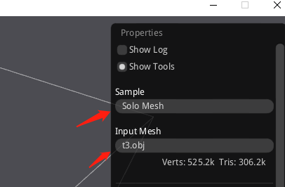
加载一个obj文件:
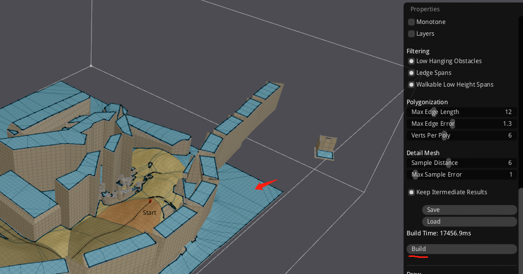
将obj文件的导航网格生成出来:
生成了之后,地图的颜色将会变化,只需要点击”Build”。有导航网格,才能去测试导航功能。
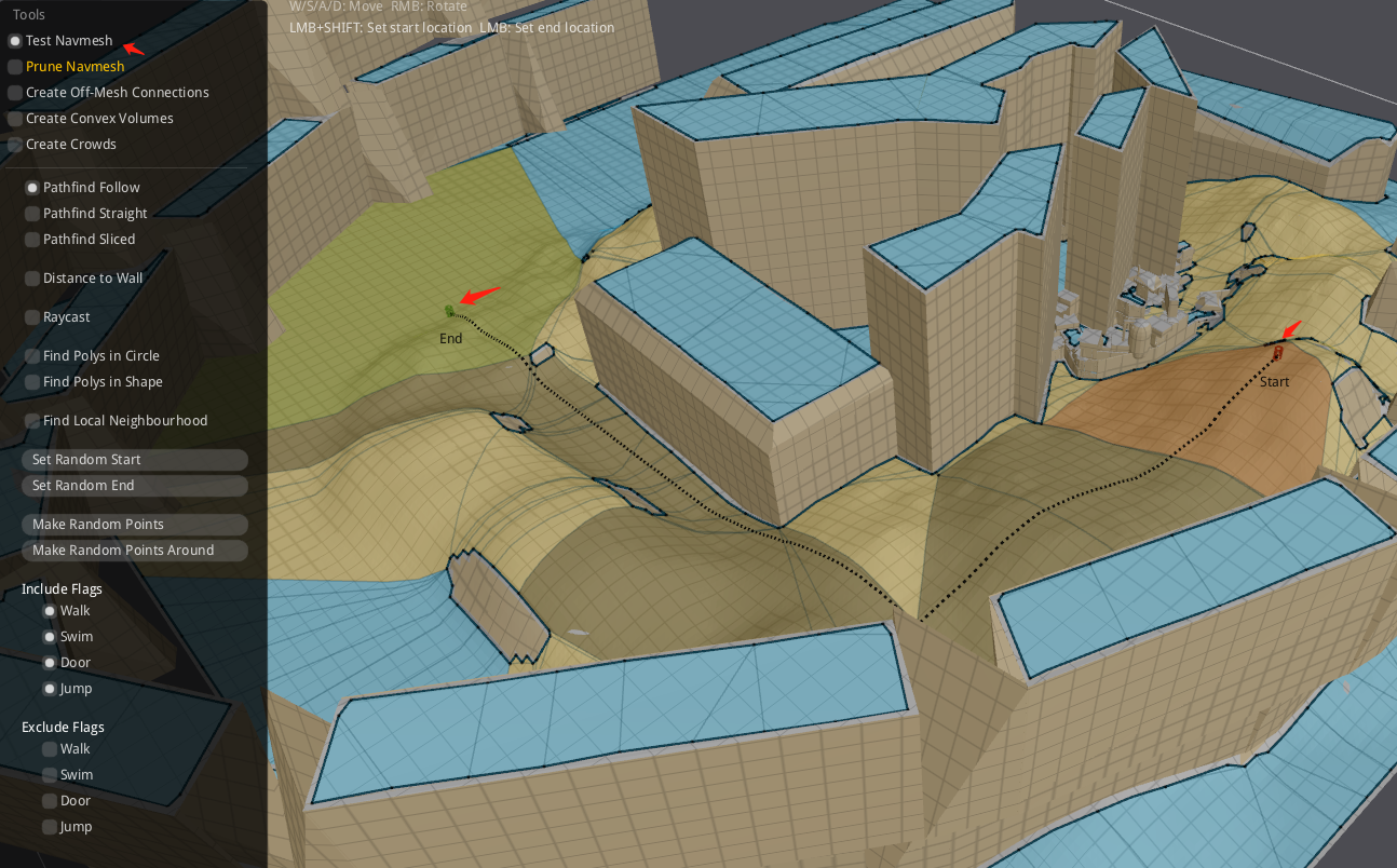
测试导航功能:
在地图上选择开始结束点;”shift+鼠标左键”
3.Recast 导航网格类型
recastnavigation中提供了3种模式的导航网格:
3.1.SoloMesh
其中SoloMesh模式是静态的导航网格,即对场景build一次之后,将导航网格缓存起来供寻路使用,后续不再允许场景的导航信息发生变化。
文件头:
1 | static const int NAVMESHSET_MAGIC = 'M'<<24 | 'S'<<16 | 'E'<<8 | 'T'; //'MSET'; |
3.2.TileMesh
TileMesh也是静态的导航网格,只是与SoloMesh相比它按tile来处理地图,算是介于SoloMesh和TempObstacles之间的一种模式
1 | // 文件名:all_tiles_navmesh.bin |
3.3.TempObstacles
TempObstacles模式可以支持向场景中动态添加或移除预设形状的阻挡物,导航网格也会随之更新(不过只支持添加阻挡物,而不支持添加新的可行走区域)在处理动态阻挡时,由于单个阻挡对地图的影响区域是有限的,所以会采用将地图切割成多个固定大小的tile,以tile为单位进行网格的生成。这样在添加或移除阻挡时,只需要处理与阻挡相交的tile,而不需要处理整个地图。
1 | static const int TILECACHESET_MAGIC = 'T' << 24 | 'S' << 16 | 'E' << 8 | 'T'; //'TSET'; |
3.4.导出Mesh的源码分析
参考官方的代码-RecastDemo部分,在右边的上部,”Sample”中下拉菜单中选择的三类(Solo Mesh、Tile Mesh、Temp Obstacles)导出方式都看明白。
3种导出方式:
1 | Sample* createSolo() { return new Sample_SoloMesh(); } |
“Build”按钮将会调用
1 | if (imguiButton("Build")) |
“Save”按钮将会把生成的网格存储到
| 类型 | 文件 | 大小 |
|---|---|---|
| Solo | solo_navmesh.bin | 240kb |
| Tile | all_tiles_navmesh.bin | 479kb |
| TempObstacle | all_tiles_tilecache.bin | 479kb |
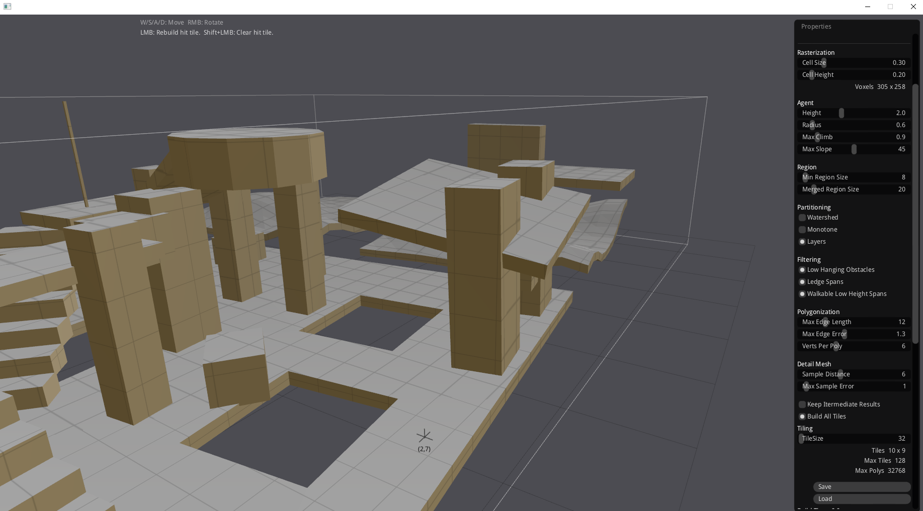
导出时候需要设置的参数:
| 变量 | 基本信息 | 备注 |
|---|---|---|
| cellsize | 方块尺寸 | 0.3 |
| cellheight | 方块高度 | 0.2 |
| agentheight | walkableHeight = agentheight/ cellheight | 2 |
| agentradius | walkableClimb = agentradius/ cellheight | 0.6 |
| agentmaxclimb | walkableRadius = agentmaxclimb/ cellheight | 0.9 |
| agentmaxslope | walkableSlopeAngle = agentmaxslope | 45 |
| regionminsize | minRegionArea = regionminsize*regionminsize | 8 |
| regionmergesize | mergeRegionArea = regionmergesize*regionmergesize | 20 |
| edgemaxlen | maxEdgeLen = edgemaxlen/cellheight | 12 |
| edgemaxerror | maxSimplificationError = edgemaxerror | 1.3 |
| vertsperpoly | maxVertsPerPoly | 6 |
| detailsampledist | detailSampleDist = detailsampledist < 0.9f ? 0 : cellsize * detailsampledist; | 6 |
| detailsamplemaxerror | detailSampleMaxError = cellheight * detailsamplemaxerror | 1 |
| partitiontype | 1 | |
| tilesize | 48 |
cellsize
方块尺寸(x,z平面上),和平面有关系。较低的值将产生较高质量的导航,但是图形扫描较慢。在文档里面记作 [vx]
cellheight
方块高度(y高程),和爬坡有关系。记录计算攀爬仰角,攀爬的高度,计算边缘都需要这个。官方文档里面记作 [vy]
agentheight
minRegionArea
最小孤岛所容纳的cell数目;
任意区域小于指定的数目,将会标记成无法行走。这个东西通常用于去删除无用几何体,比如桌子的顶部,盒子的顶部等等。
值域:[Limit: >=0] 作用域:[Units: vx],vx代表平面;
mergeRegionArea
如果有可能性的话,任意区域如果cell的数目小于它,将会被融合到比它大的区域里面。
值域:[Limit: >=0] 作用域:[Units: vx]
edgemaxlen
沿网格边界的轮廓边缘的最大允许长度。 [Limit: >=0] [Units: vx].
这个将会让边缘更加趋于直线。如果想关闭这个功能将值设置成0。
partitiontype
分区方式
Watershed 分水岭方式
enum SamplePartitionType SAMPLE_PARTITION_WATERSHED = 0
大意就是从地势的最低点开始灌水,水漫过的区间若与原区域相邻则认为是同一区域,否则认为是一个新的区域。分水岭算法通常用于图形处理领域,基于图像的灰度值来分割图像。
Monotone 单调方式
enum SamplePartitionType SAMPLE_PARTITION_MONOTONE = 1
Layers 分层方式
enum SamplePartitionType SAMPLE_PARTITION_LAYERS = 2
原文释义:
1 | Partition the heightfield so that we can use simple algorithm later to triangulate the walkable areas. |
tilesize
每块tile再xz平面上的size。[Limit: >= 0] [Units: vx].
这个值旨在编译出多tile mesh的时候生效(temp obstacles/tiles)。
4.包围盒分类
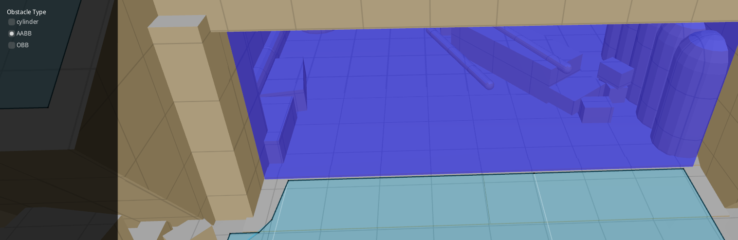
4.1.AABB
AABB算法的全称是 - axis aligned bounding box (轴对齐-边界盒)AABB 包围盒是与坐标轴对齐的包围盒, 简单性好, 紧密性较差。
我们在具体使用的时候,发现如果地形上有一些起伏,最好能通过AABB方式来,这样确保地图中的位置被严格的堵住。
4.2.OBB
OBB 包围盒: OBB(oriented bounding box 方向矩形边界框) 碰撞检測方法紧密性是较好的, 可以大大降低參与相交測试的包围盒的数目, 因此整体性能要优于AABB 和包围球, 而且实时性程度较高。
OBB在堵路的时候,如果有楼梯类似的地势,将无法做到将导航切割。
阅读 Export Recast Navigation Data from UE4
Library: ue-recast-detour这个是从 UE 代码中抽取出的 recast detour 库,在 UE 源码的路径下为 Runtime/Navmesh/Detour,主要目的是保证 UE 客户端与外部服务器的验证方法一致。只将solo方式的导航。
其实在UnrealEngine4的源代码中是有一份NavigationSystem,Navmesh。github-UE4-Navmesh。可以直接在ue4的引擎代码里面找到动态阻挡相关的逻辑。
阅读RecastDemo
最近在看recast的阻挡相关知识,其实这块最好能扩展一下工具的绘制功能。具体文件目录在recastnavigation\DebugUtils\Include\DebugDraw.h
能支持的绘制类型
1 | enum duDebugDrawPrimitives |
最终调用的gl函数
1 | switch (prim) |
最终完成绘图的就是底层的SDL_opengl库的函数。我们这里是使用的SDL 2.0.14版本。
Simple DirectMedia Layer is a cross-platform development library designed to provide low level access to audio, keyboard, mouse, joystick, and graphics hardware via OpenGL and Direct3D.
绘制实例
绘制AABB方块
通过四边形来拼凑出来。
1 | if (ob->type == DT_OBSTACLE_BOX) |
绘制圆柱体
圆柱体绘制的时候,是按照16等分的圆面,然后用三角形拼凑出来的。
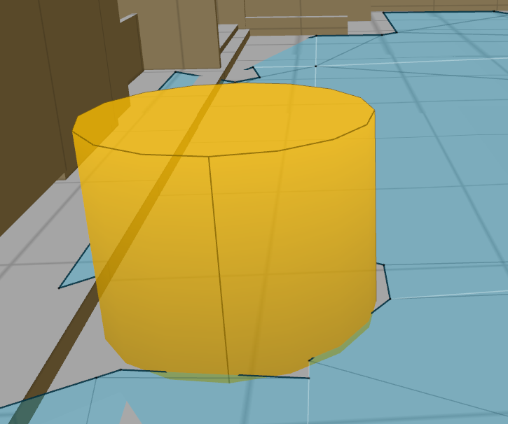
1 | else if (ob->type == DT_OBSTACLE_CYLINDER) |
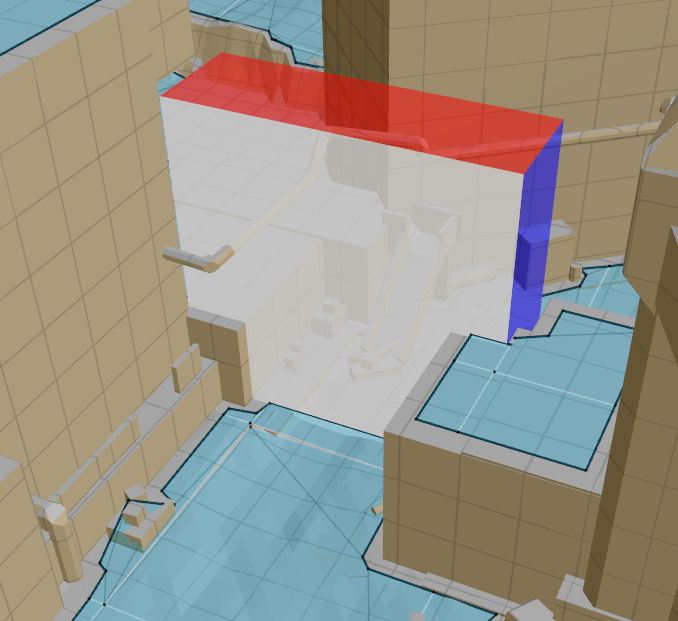
依葫芦画瓢OBB
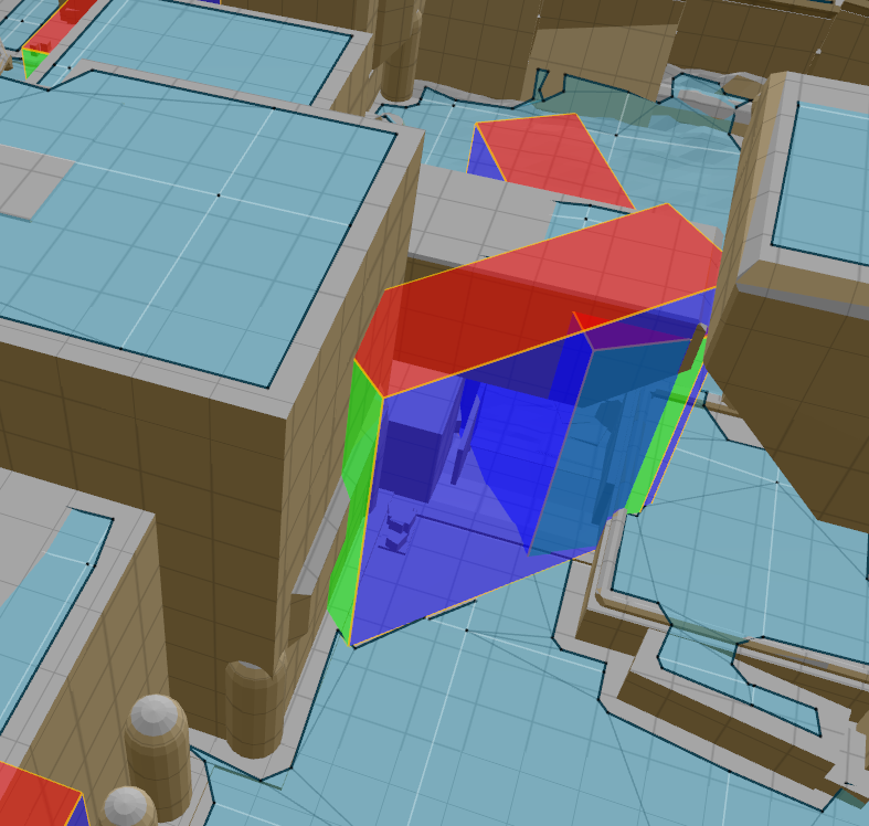
1 | // 绘制OBB立方体 |
阅读导出时系数
agent
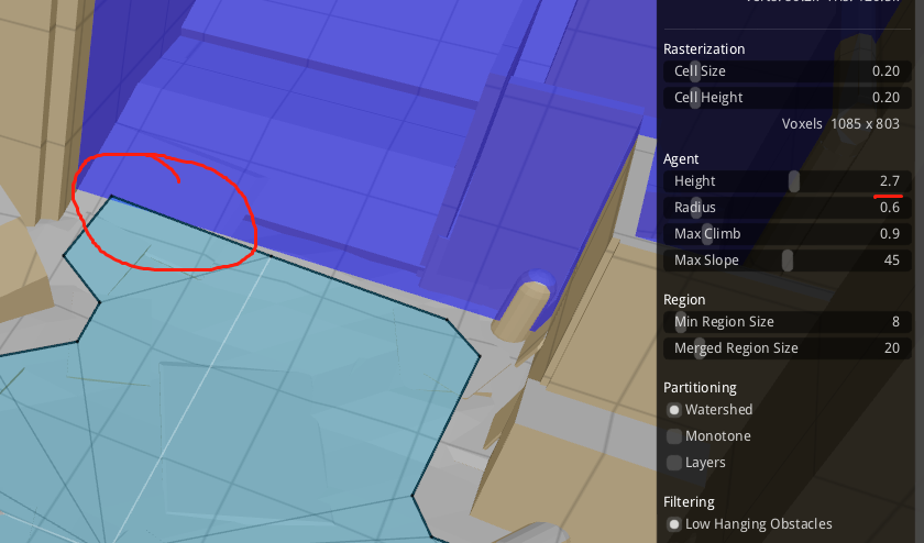
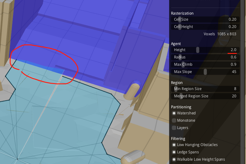
修改了agent的半径之后,就能让AABB方式的动态墙切断navimesh。
imgui用法
如何使用单选框
1 | class Sample { |
obb如何被导出
问题描述
相同体型的阻挡信息,长宽高为 10m2m6.5m。AABB动态阻挡能隔断mesh,但是OBB动态阻挡(旋转90°)无法阻断mesh。
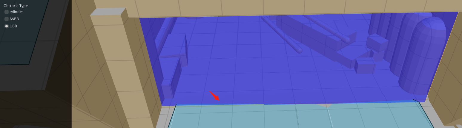
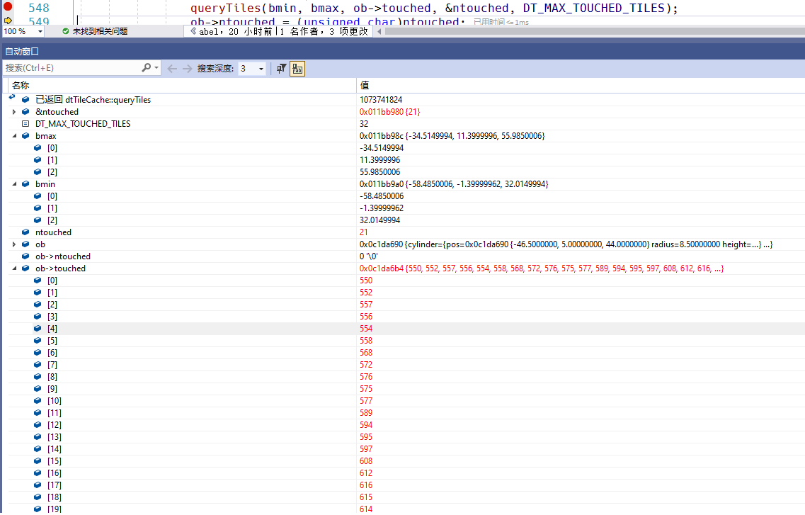
使用OBB的时候,将会在获取触碰到的titles有21个。
使用AABB的时候,将会获取触碰到的titles只有6个。
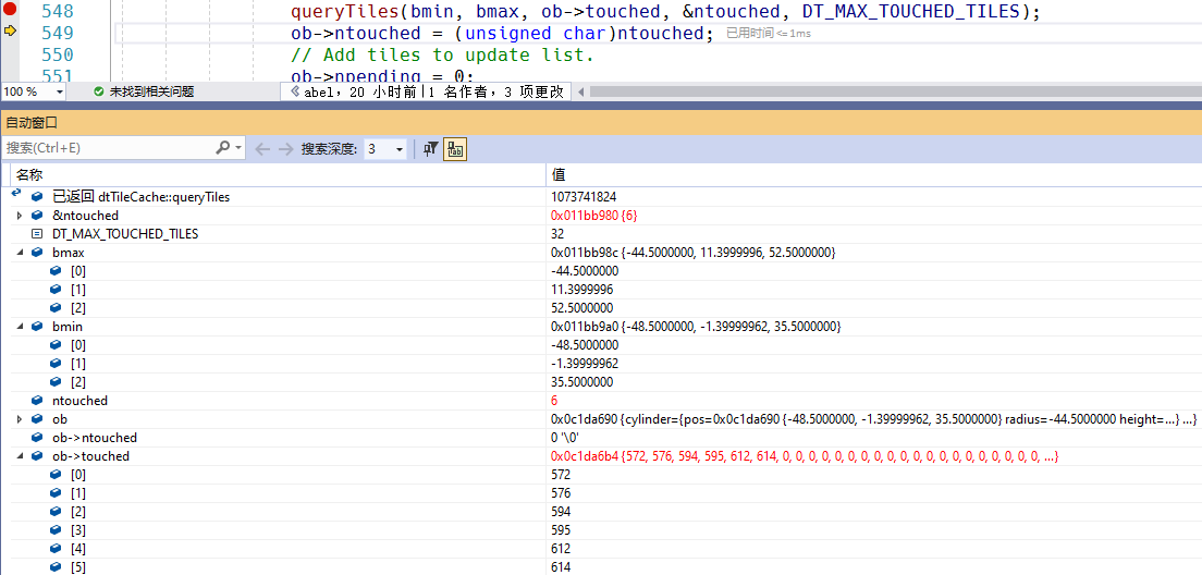
源码里面只能让一个阻挡点碰撞到8个tiltes。
1 | static const int DT_MAX_TOUCHED_TILES = 8; |
所以OBB少去检查了titles造成了问题。如果我们将缓冲区加大之后就不会有问题。
为啥OBB需要碰撞这么多点?原因还是在于这些代码:
1 | const dtObstacleOrientedBox &orientedBox = ob->orientedBox; |
这段代码的意思是,OBB的X,Z的最大值1.41,形成的一个正方形。所以会比相同的AABB的形状大很多。10m1.141见方的一个方块(130.1881平方米),而AABB是 10m*2m(20平方米),大了6.5倍。我这里先使用矩阵把矩形框旋转,投影到X,Z轴上。让bounding更小,只要不突破8个上限,就能正常工作。
参考
- [1] recastnavigation
- [2] premake
- [3] SDL
- [4] recastdetour手册
- [5] 游戏的寻路导航 1:导航网格
- [6] recastNavigation读书笔记1
- [7] CritterAI
- [8] B站讲解RecastDemo如何使用
- [9] 从零开始学习导航网格
- [10] AABB&OBB包围盒
- [11] 生成寻路网格的配置
- [12] 手动创建navmesh
- [13] navmesh参数
- [14] ue-navmesh
- [15] 循迹研究室-Export Recast Navigation
- [16] libIGL